5 CNC Machining Mistakes That Will Ground Your Drone Before It Flies
From wrong material selection to sloppy tolerance management, these five CNC machining mistakes silently sabotage drone builds before they ever leave the ground. Learn exactly what goes wrong — and how to fix each issue before it costs you a prototype or an entire production run.
The five CNC machining mistakes most likely to ground your drone are: choosing the wrong material grade, ignoring vibration-induced tolerance stack-up, using incorrect feed rates that create micro-stress fractures, neglecting deburring and edge finishing, and failing to account for thermal expansion during flight. Every one of these errors is preventable at the CAM programming or material selection stage — yet they collectively account for the majority of first-flight failures in custom drone frames. Below, we break each mistake down with specific numbers, real-world scenarios, and actionable fixes so your next build flies on schedule.
Mistake #1: Picking the Wrong Alloy (or Composite) for the Job
Here’s a stat that surprises people: roughly 40% of drone frame redesigns trace back to a material choice made in the first 15 minutes of a project. Grabbing whatever 6061 aluminum bar stock is sitting on the shelf feels efficient — until the motor mount cracks after 30 hours of vibration testing.
Why Material Grade Matters More Than Material Type
6061-T6 aluminum is the default for a reason: it machines beautifully, anodizes well, and costs next to nothing. But it has a fatigue limit around 97 MPa. For a quadcopter arm experiencing cyclic loading from motor vibration at 200–400 Hz, that number can become dangerously relevant. 7075-T6 nearly doubles the tensile strength (572 MPa vs. 310 MPa) and offers a meaningfully higher fatigue threshold — critical for arms, landing gear, and any structural member that absorbs impact.
Carbon fiber composites flip the equation entirely. They’re lighter and damp vibration far better, but CNC routing carbon fiber demands diamond-coated tooling, dust extraction, and completely different feed strategies. Machine it like aluminum and you’ll delaminate layers, creating invisible weak points that fail catastrophically mid-flight.
Real-World Example
A commercial survey drone manufacturer we worked with initially spec’d their entire frame in 6061-T6 to simplify procurement. After two field failures — both cracked motor mounts — they switched the mounts and arm clamps to 7075-T6 while keeping the center plate in 6061. Total material cost increase: about $12 per unit. Failure rate dropped to zero over the next 500 units. The lesson? Use the right alloy in the right place, not one alloy everywhere.
Check out our resources page for detailed material specification guides tailored to drone applications.
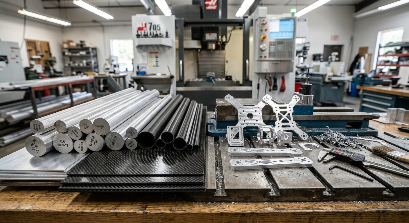
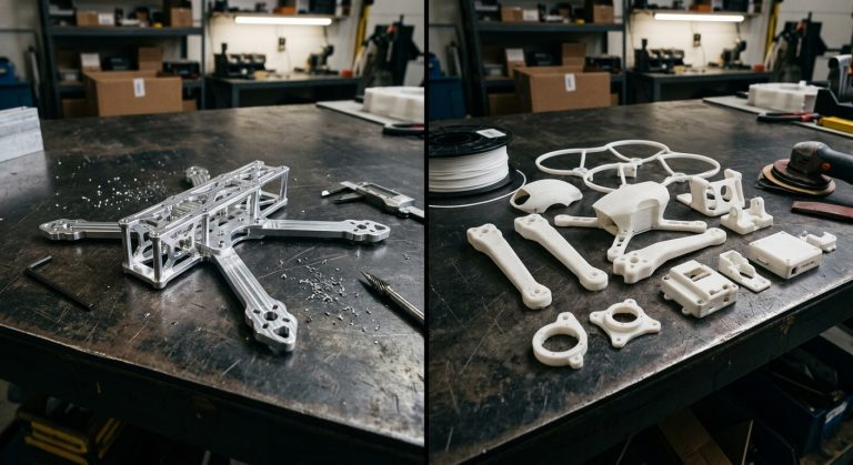
Various aluminum alloy stock and carbon fiber sheets with machined drone parts on a CNC workshop table
Mistake #2: Tolerance Stack-Up That Vibration Turns Into Failure
A ±0.1 mm tolerance on any single part is perfectly fine. Stack six of those parts into an assembled drone frame, and you could be looking at ±0.6 mm of cumulative deviation. Now spin four motors at 8,000 RPM on that frame. The vibration doesn’t forgive slop — it amplifies it.
How Tolerance Stack-Up Kills Flight Performance
Drone flight controllers rely on IMU (inertial measurement unit) data to maintain stability. When a frame has excessive play at joint interfaces — even 0.3 mm total — the IMU reads mechanical noise as real motion. The result: oscillation, PID tuning nightmares, and in extreme cases, a fly-away. This isn’t theoretical. It’s the number-one complaint from custom drone builders who outsource CNC work to general-purpose job shops.
The Fix: Design for Assembly Tolerance
Tighten critical mating surfaces to ±0.025 mm. Yes, it costs more per part. But you’re tightening only the interfaces — motor mount holes, flight controller mounting points, and arm-to-center-plate joints. Leave non-critical features at ±0.1 mm. This selective approach typically adds 10–15% to machining cost, not the 50%+ that blanket tight tolerances would demand.
Use dowel pins or precision locating features rather than relying on bolt holes alone. A 3 mm reamed dowel hole with an H7/h6 fit gives you repeatable alignment every single assembly, taking the guesswork out of tolerance management.
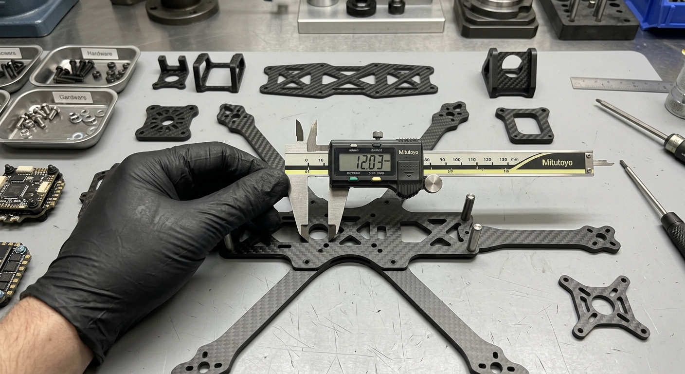
Precision CNC-machined drone frame components with dowel pins and digital caliper showing tight tolerances
Mistake #3: Aggressive Feed Rates That Create Hidden Micro-Fractures
Speed kills — literally, in this context. Pushing a 6 mm end mill through 7075 aluminum at 3,000 mm/min with a 50% radial engagement might clear material fast, but it generates enough heat and cutting force to induce micro-stress fractures along thin walls. These fractures are invisible to the naked eye and often pass basic visual QC. They reveal themselves 20 flights later when an arm snaps cleanly in half.
The Physics Behind the Problem
Drone frame components are typically thin-walled — 1.5 mm to 4 mm in most designs. Thin walls deflect under cutting pressure, and that deflection work-hardens the aluminum surface. Work-hardened aluminum is harder but brittle. Combine that with residual tensile stress from aggressive machining, and you have a part that looks perfect but is structurally compromised.
Optimal Parameters for Drone-Grade Parts
For 7075-T6 with a 6 mm carbide end mill:
Spindle speed: 10,000–12,000 RPM
Feed rate: 1,500–2,000 mm/min
Axial depth of cut: 1.0–1.5× tool diameter
Radial engagement: 25–35% for finishing passes on thin walls
Use climb milling — it reduces deflection forces on thin sections
These numbers aren’t conservative for the sake of it. They’re the sweet spot where material removal rate stays productive and surface integrity stays intact. A drone arm machined at these parameters will show smooth, consistent chip formation — no blue chips (heat), no chatter marks (vibration), no deflection artifacts.
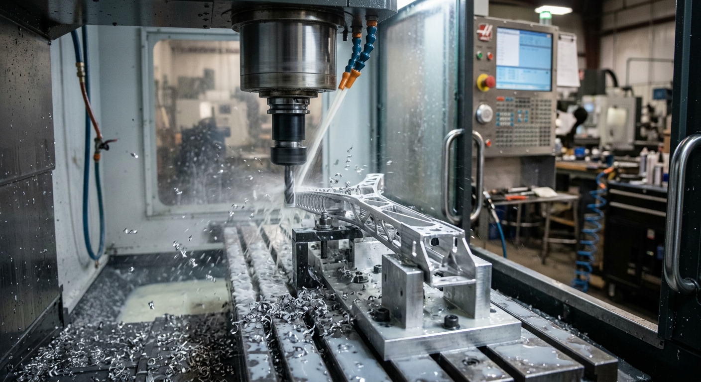
CNC milling machine cutting a thin-walled aluminum drone arm with visible aluminum chips
Mistake #4: Skipping Deburring and Edge Finishing
This one sounds minor until a razor-sharp burr slices through a motor wire harness at 15,000 feet AGL. It happens more often than any manufacturer wants to admit.
Burrs Are Stress Risers, Not Just Cosmetic Issues
A burr on the edge of a motor mount hole isn’t just ugly — it’s a crack initiation point. Under cyclic vibration loading, cracks propagate from stress concentrations. A 0.2 mm burr can reduce the fatigue life of a hole edge by 30–60%, depending on the alloy and loading conditions. For structural holes (arm bolts, motor mounts), that’s unacceptable.
Best Practices for Drone Frame Finishing
Chamfer all structural edges — 0.3–0.5 mm × 45° minimum. Program it into the CAM toolpath; don’t rely on hand deburring.
Tumble-finish small parts — vibratory tumbling with ceramic media for 30–60 minutes removes micro-burrs and imparts mild compressive stress (which actually improves fatigue life).
Inspect wire-routing channels — any slot, groove, or hole that a wire passes through needs a radius or chamfer. Period.
For instance, a racing drone team we consulted with traced intermittent power dropouts to a single burr inside a wire pass-through slot on their CNC’d center plate. The burr slowly abraded the silicone insulation on their 14 AWG power lead over about 40 flights until it shorted against the frame. A $0.30 chamfering operation would have prevented a $2,000 crash.
If you’re unsure about finishing standards for your application, reach out to our team for guidance on spec’ing edge requirements.
Mistake #5: Ignoring Thermal Expansion During Flight Operations
Most drone builders design and machine parts at a comfortable 20°C shop temperature. But drones operate in environments ranging from -20°C Arctic surveys to +55°C desert inspections. Aluminum’s coefficient of thermal expansion (CTE) is roughly 23.6 µm/m/°C. That means a 300 mm aluminum arm grows or shrinks by about 0.25 mm over a 35°C temperature swing. Doesn’t sound like much? It is when your motor mount bolts are torqued to spec at room temperature.
What Actually Happens in the Field
In cold conditions, aluminum contracts faster than the steel bolts holding the frame together. Bolt preload increases, potentially crushing inserts or distorting thin mounting flanges. In extreme heat, the frame expands, bolt preload drops, and fasteners can loosen — especially if thread-locking compound wasn’t applied.
Carbon fiber makes this worse, not better. Its CTE is near zero (or even slightly negative in some layups). Bolt a carbon fiber plate to an aluminum bracket, heat the assembly by 40°C, and the aluminum grows while the carbon fiber doesn’t. The result is bowing, stress at bolt holes, and eventual cracking of the aluminum component.
Design Countermeasures
Use slotted mounting holes on at least one axis for mixed-material joints. This allows differential expansion without building stress.
Specify Belleville washers on critical fasteners — they maintain consistent preload across a temperature range.
Torque fasteners at the expected operating midpoint temperature when possible, or use thermal-compensating torque specs.
These aren’t exotic solutions. They’re standard practice in aerospace — and your drone is, after all, an aircraft.
Material Selection at a Glance
Choosing between aluminum alloys and carbon fiber composites is the first decision that cascades into every other machining parameter. The comparison table below summarizes the key properties that matter for drone frame components. Use it as a quick reference when spec’ing your next build.
The right answer is almost always a hybrid approach: aluminum for high-machinability structural nodes, 7075 for high-stress points, and carbon fiber for vibration-sensitive surfaces and weight-critical plates. Don’t let material simplicity tempt you into a one-alloy-fits-all approach — that’s Mistake #1 all over again.
Quality Control: Catching These Mistakes Before First Flight
Knowing the mistakes is half the battle. Catching them before a drone leaves the bench is the other half. Here’s a practical QC checklist tailored specifically to CNC-machined drone components:
Dimensional Verification
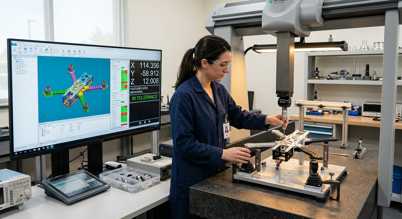
CMM (coordinate measuring machine) inspection on first-article parts for all critical mating surfaces
Go/no-go gauge checks on dowel holes and motor mount bores for every production part
Flatness check on center plates — max 0.05 mm over 200 mm for flight controller mounting surfaces
Surface and Structural Integrity
Dye penetrant inspection (DPI) on high-stress areas if fatigue life is critical — especially 7075 parts machined at aggressive parameters
Surface roughness measurement: Ra 0.8 µm or better on mating surfaces, Ra 1.6 µm acceptable on non-critical faces
Visual and tactile burr inspection on every hole and edge, with rejection criteria documented
Assembly Validation
Trial assembly of one frame per batch to verify tolerance stack-up in practice
Vibration test at expected motor RPM range for 15 minutes minimum before first flight
Bolt torque audit after vibration test — any fastener that lost more than 10% preload indicates a design or finishing issue
This checklist adds maybe 20 minutes per batch. Compared to the cost of a field failure — or worse, a crash that damages payload equipment worth tens of thousands — it’s the cheapest insurance you’ll ever buy.
Coordinate measuring machine inspecting CNC-machined drone frame parts in a metrology lab
Build It Right the First Time
Every one of these five mistakes shares a common thread: they’re cheap to prevent and expensive to fix after the fact. Choosing the right alloy for each component, tightening tolerances only where they matter, dialing in conservative-but-productive feed rates, finishing every edge properly, and designing for thermal reality — none of this is cutting-edge science. It’s disciplined engineering applied to a demanding application.
The drone industry moves fast, and the temptation to skip steps is real. But a drone that flies reliably on its first test is worth infinitely more than one that looks good on the bench and fails in the field.
At Dronecnc Demo, we specialize in exactly this intersection of CNC precision and drone performance. Whether you’re prototyping a new frame design or scaling to production volumes, get in touch with our engineering team to make sure your machining strategy matches your flight ambitions.